Labyrinth seals are widely used in turbomachinery to control leakage and contribute to overall system stability. Their performance, however, is governed by highly complex flow phenomena such as separation, recirculation, and shear layer interactions. Traditional analytical models often fall short in predicting these effects, as they rely on simplified leakage correlations and do not capture the full range of dynamic forces acting on the rotor.
In design practice, experimental testing provides the most reliable data, but it is expensive and not always feasible in early development stages. High-fidelity 3D CFD can offer detailed insights, yet it demands significant computational resources. For this reason, a two-dimensional CFD approach is considered in this study. By simulating a stepped labyrinth seal and comparing the results against the experimental data of (Kwanka, 2000), the aim is to establish a method that delivers fast yet sufficiently accurate predictions. Such an approach provides engineers with an early indication of sealing performance and dynamic behavior trends before moving to more resource-intensive analyses.
Geometry
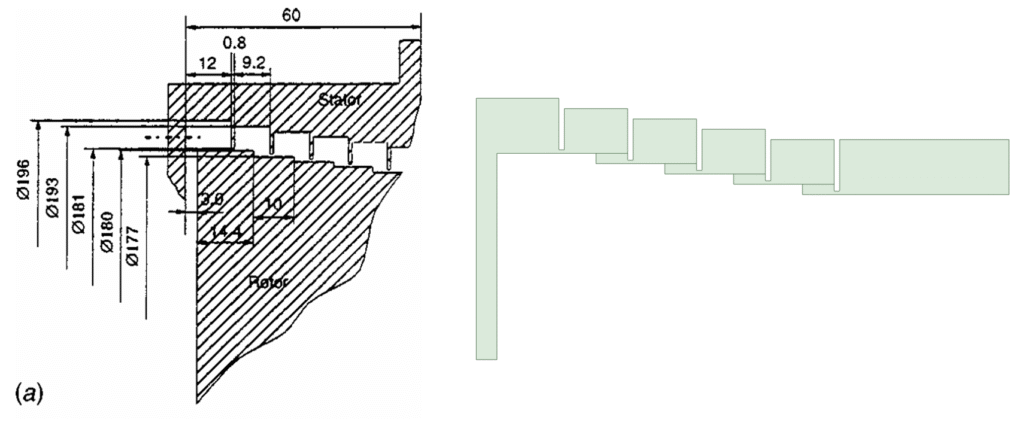
The configuration analyzed is a stepped labyrinth seal with a teeth-on-stator design, modelled after the reference geometry presented by Kwanka, 2000. The seal is created in ANSYS SpaceClaim.
To better reflect manufacturing practice, a corner radius of  was applied to all sharp edges, avoiding unrealistic perfectly sharp corners. Furthermore, refinement lines were introduced into the model to support targeted mesh refinement in regions where shear layers are expected to develop downstream of the steps.
Grid generation
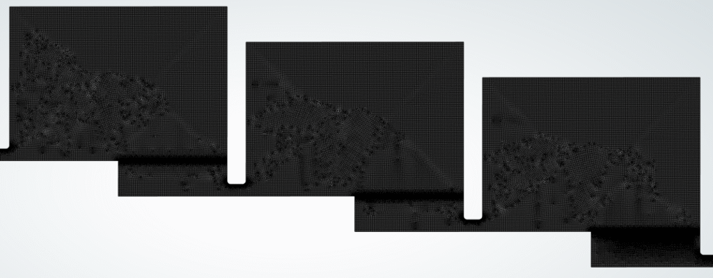
The mesh was generated using a multizone approach, resulting in a structured grid with high element quality. This ensured smooth transitions between regions of different refinement levels while maintaining good numerical stability. The final grid contained approximately 350,000 cells, with an orthogonal quality above 0.47 and a maximum aspect ratio below 5.
To resolve critical flow structures, additional refinement was introduced in the shear flow regions downstream of the steps, consistent with the refinement lines defined during the geometry setup. Near-wall treatment was based on wall functions, with the grid designed for a target  . This approach balances accuracy and computational cost, supporting the goal of obtaining reliable predictions within a fast simulation workflow.
Grid independence study
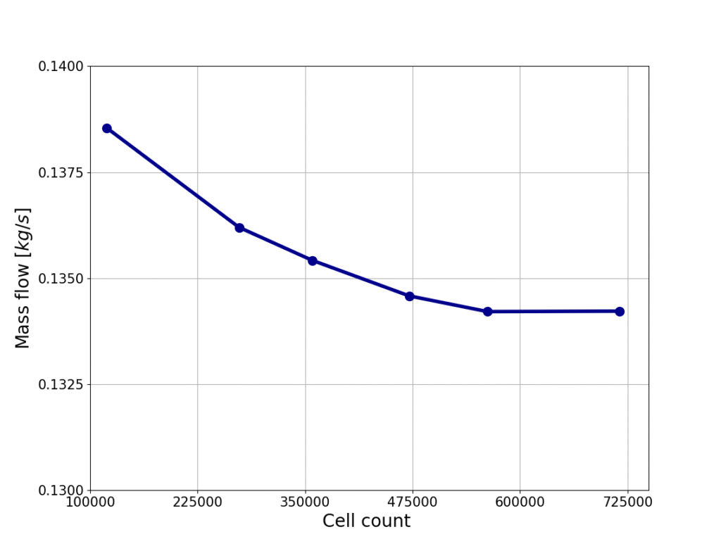
A mesh refinement study was conducted to verify that the predicted results are independent of grid resolution. Several meshes ranging from 125,000 to 725,000 cells were evaluated, and the corresponding mass flow rates through the seal were compared.
As shown in the figure below, the predicted mass flow decreases with increasing grid density, but the variation becomes negligible beyond approximately 350,000 cells. The difference in mass flow between the 350,000-cell mesh and the finest 725,000-cell mesh is less than 1%, confirming that further refinement does not significantly improve accuracy.
On this basis, the mesh with 350,000 cells was selected for the final simulations, as it provides an optimal balance between accuracy and computational efficiency.
Turbulence model
The turbulence was modeled using the Realizable k-ε formulation, which performs better than the standard model for internal flows with interacting shear layers, such as those in labyrinth seals. Scalable wall functions ensured that the first near-wall node remained in the logarithmic region, providing consistent wall treatment at a lower computational cost. To limit excessive turbulence generation in separated zones, the production limiter was applied. Finally, a compressibility correction was included to account for the influence of locally high Mach numbers in the narrow seal clearances.
Material properties and boundary conditions
The working fluid was air, consistent with the experimental investigations of Kwanka (2000). To capture compressibility effects, the density was modeled using the ideal gas law. The viscosity was treated as temperature-dependent and evaluated using the Sutherland law, while all remaining fluid properties were considered constant and kept at the solver’s default values.
The inlet was defined using a total pressure boundary condition, with the pressure level varied to match the experimental test cases of Kwanka (2000). At the outlet, an atmospheric static pressure was prescribed using the average pressure specification to ensure numerical stability. In addition, the rotor was modeled with a rotational speed of 750 rpm, consistent with the experimental setup.
Solver settings
The following model and solver settings are selected:
- Steady state pressure based solver
- Viscous model: k-epsilon Realizable with scalable wall functions, production limiter and, and the compressibility effects enabled
- Pressure velocity coupling: Coupled
- Gradient: Least squares cell based
- Pressure: PRESTO!
- Density: Second Order Upwind
- Momentum: Second Order Upwind
- Turbulent kinetic energy: Second Order Upwind
- Turbulent dissipation rate: Second Order Upwind
- Higher Order Term Relaxation enabled
- Default under relaxation factors
- Initialization: Hybrid
Convergence
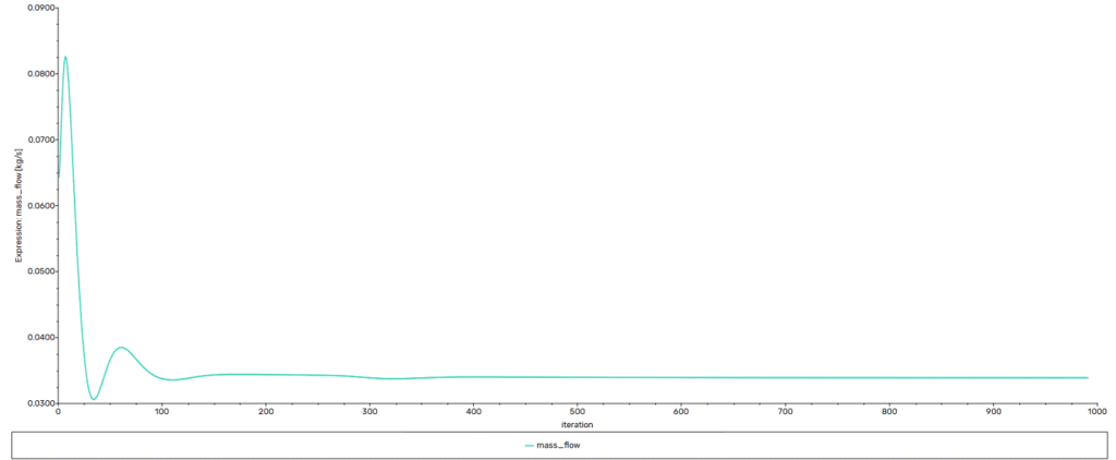
The residuals showed a steady reduction of three to six orders of magnitude, with the energy equation converging cleanly to  . Residuals for velocity, k, and, epsilon displayed minor oscillations after approximately 500 iterations. These fluctuations are attributed to the naturally unsteady recirculation within the seal cavities rather than numerical instability.
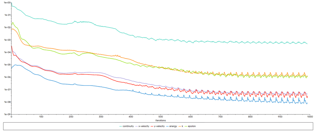
The mass imbalance shows that what is flowing into the computational domain also exits the computational domain. This indicates that the continuity equation is sufficiently satisfied.
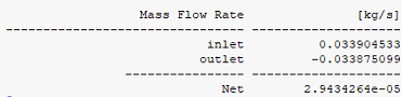
The monitored engineering quantity, the leakage rate, remained stable. Based on these criteria, the solution was judged to be sufficiently converged for engineering evaluation.
Results
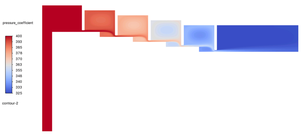
The contour plot below illustrates the pressure coefficient distribution across the stepped labyrinth seal at the lowest pressure ratio. Each tooth and cavity acts as a throttling element, producing a stepwise pressure drop from inlet to outlet. This demonstrates the sealing principle directly: energy is dissipated through repeated contractions, expansions, and cavity vortices, reducing the pressure and kinetic energy available to drive leakage.
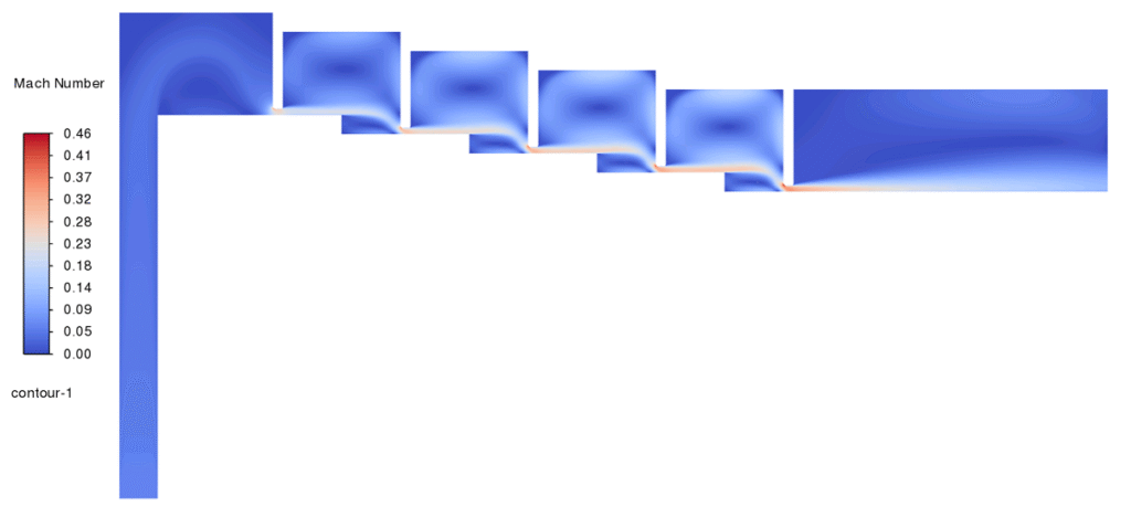
The second contour, also taken at the lowest pressure ratio, presents the Mach number field. Local accelerations up to about 0.45 occur in the narrow clearances, while the cavities are filled with large recirculating vortices. These vortices are central to the dissipation process, highlighting the strong interaction between the high-speed jets through the teeth and the separated flows inside the cavities.
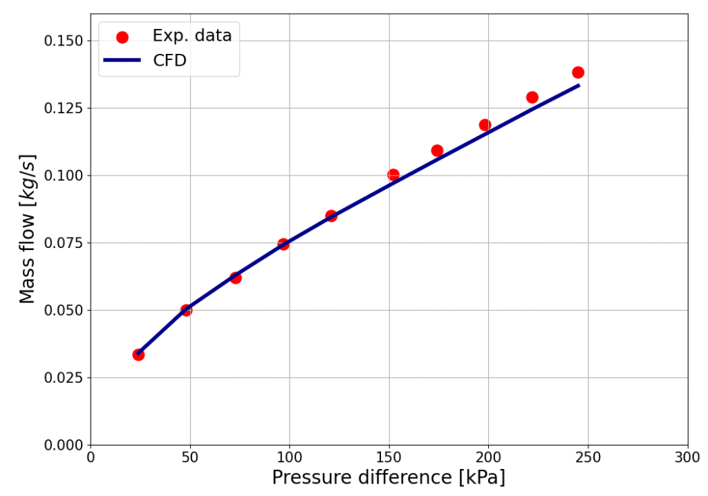
The final figure compares the predicted mass flow rate against experimental measurements for varying pressure ratios. The CFD results align closely with the data of Kwanka (2000), with a maximum deviation of only 3.7%, while capturing both the trend and magnitude of leakage. This level of agreement indicates that the model is able to represent the leakage behavior of the stepped labyrinth seal with good accuracy.
Conclusion
This study shows that a relatively simple two-dimensional CFD setup can capture the main flow mechanisms in a stepped labyrinth seal with a teeth-on-stator design. By combining the Realizable k-εk\text{-}\varepsilonk-ε model, scalable wall functions, and a carefully constructed mesh, the simulation reproduced the pressure distribution, shear layer development, and leakage characteristics observed in experiments.
From a practical perspective, the results demonstrate that reliable leakage predictions can be obtained without resorting to resource-intensive 3D models. This makes the approach well suited for early-stage seal design, parametric studies, and performance screening, where turnaround time and computational efficiency are critical.
While the method does not resolve all fine-scale details of the flow, the good agreement with experiments, within 4% deviation, confirms its usefulness as an engineering tool for evaluating labyrinth seal performance.