Getting the transition point right is essential, because it directly sets the skin-friction drag. A laminar plate carries far less shear than a turbulent one, so moving the onset even a short distance can change total drag by a large margin. In real flows, free-stream turbulence often pushes transition forward, a process known as bypass transition.
The ERCOFTAC T3A case was designed to capture this effect in a clean, repeatable way. A flat plate under zero pressure gradient is exposed to about 3% turbulence at 5.4 m/s, with carefully controlled inlet conditions. This makes it one of the most trusted benchmarks for CFD. For skin-friction predictions, it provides the reference data needed to judge whether a model captures transition at the right location. This case remains a cornerstone for practical drag prediction.
Geometry
Below is the meshing-ready domain used for the T3A flat-plate case. The plate begins at the origin and extends 1,700 mm in the streamwise direction, while the domain height is 250 mm. An upstream block of 50mm is included to allow flow development before the leading edge. The long block is divided into sub-sections to provide high resolution near the plate start and within the wall-normal growth region.
The boundary-layer block height is based on the fully turbulent flat-plate correlation for the 99% thickness, with an added 30% safety margin:
This ensures that the entire boundary layer is fully contained, keeps mesh growth in the wall-normal direction under control, and leaves the outer core region more uniformly meshed.

Grid generation
A fully structured mesh was generated for the domain. In the boundary-layer block, a growth rate of 1.063 was applied, starting with a first cell height of 0.047 mm, which ensures a  well below unity. The core region is meshed more uniformly, with a slight bias toward the top boundary. The mesh quality is high, with an orthogonal quality of 1.0 and a maximum aspect ratio of 58. In total, the grid contains about 195,000 cells, providing a balanced compromise between accuracy and computational cost.

Turbulence model
The simulation uses the k–ω SST model together with the γ-transition transport equation. This combination is well suited to transitional flat-plate boundary layers, as it provides accurate near-wall resolution with  while maintaining robustness in the free-stream through the SST blending. The γ-transition model introduces a dedicated transport equation that enables the prediction of laminar–turbulent transition under elevated free-stream turbulence, which is the defining feature of the ERCOFTAC T3A case. To avoid spurious turbulence generation in regions of pure shear, the Kato–Launder production limiter is applied.
Material Properties and Boundary Conditions
The fluid density is set to  and the dynamic viscosity to
  , yielding a kinematic viscosity of
  , consistent with the T3A reference. At the inlet, a uniform velocity of
  is prescribed with a
  turbulence intensity and a turbulent viscosity ratio of
  . These settings follow the guidance and correlations presented by Langtry and Menter, ensuring that the inflow turbulence level and viscosity ratio are compatible with the transition model and with the ERCOFTAC T3A inflow conditions.
Solver settings
The following model and solver settings are selected:
- Steady state pressure based solver
- Viscous model: k-
 transition SST with the Kato-Launder production limiter enabled
 - Pressure velocity coupling: SIMPLEC
- Gradient: Least squares cell based
- Pressure: Second Order
- Density: QUICK
- Momentum: QUICK
- Turbulent kinetic energy: QUICK
- Turbulent dissipation rate: QUICK
- Higher Order Term Relaxation enabled
- Default under relaxation factors
- Initialization: Hybrid
Convergence
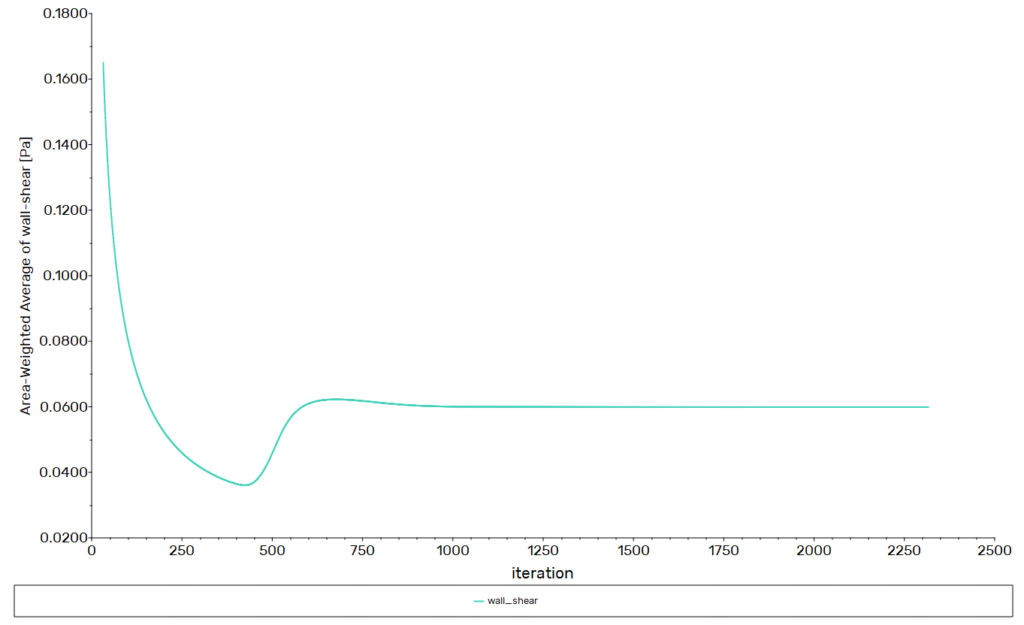
Convergence is assessed by checking the residual behavior, a quantities of interest, and mass conservation. The residuals exhibit a monotonic decline and approach the limits of computer accuracy.
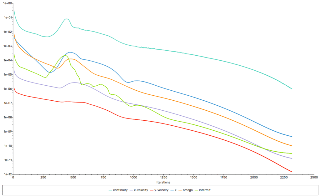
Te graphs below reveal that the final value ahas been reached within 1000 iteration.
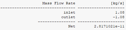
The mass imbalance shows that what is flowing into the computational domain also exits the computational domain. This indicates that the continuity equation is well satisfied.
Results
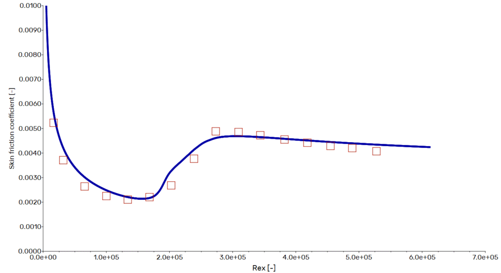
The computed skin-friction curve follows the expected transitional signature: an initial laminar decay to a minimum of about  at
at  , a sharp rise as transition sets in around
  , and a gradual decline through the fully turbulent region. The post-transition plateau peaks near
  at
at  , then slowly tapers with increasing
  .
.
Across the transitional and turbulent range, the CFD line tracks the ERCOFTAC measurements closely, typically within a few percent, capturing both the onset location and the magnitude of  . For a case driven by bypass transition at free-stream turbulence, this level of agreement is strong evidence that the SST–γ model and near-wall resolution are calibrated correctly for skin-friction prediction.
Conclusion
A compact 2D, wall-resolved RANS setup with k–ω SST plus γ-transition delivers engineering-grade predictions of the transition onset for the T3A flat plate under specified free-stream turbulence. The model captures the laminar decay, onset, and post-transition skin-friction trend without heavy computational cost.
Practically, this enables rapid sensitivity studies to turbulence intensity, early drag budgeting, and confident selection of inlet conditions for tests or scale models. In short, the approach pairs quick turnaround with trustworthy transition placement, exactly what is needed for front-end aerodynamic and thermal design decisions.